Ok, so carrying on from the post below, I attempted to re-orient vehicle, (or rather, what will be a block to simply calculate weight of the vehicle and handle player input) based on the impact normal of a ray trace.
Ended up getting largley stuck on it over the weekend, and even ended up making a help request on the UE4 answer hub to see if I could gain any insight into how to do this. Though sadly the advice I was given wasn't very helpful, as it produced the same results as I was already getting. The character would re-orient correctly in one direction, ie. It would look up a slope, but maintain the rotation when looking down the slope.
(UE4 Answer Hub thread)
Whilst the assistance I got wasn't helpful, I did end up having a eureka moment.
The whole point of using a single ray trace was twofold, one it would cut down on the total number of raytraces I was drawing (7 off the old physics model), But also to lower the number of physics calculations that were being performed (5 that interacted with the ray traces) with the aim to improve performance (cpu wise) as well as vehicle handling)
The other reason was that the old suspension to keep the vehicle stable had to apply the force at a very large offset from the vehicle itself, meaning it would push itself off the walls of the track whenever it went near them. Having a singular upwards force at the center of the vehicle and using rotators to stabilize it would solve this problem.
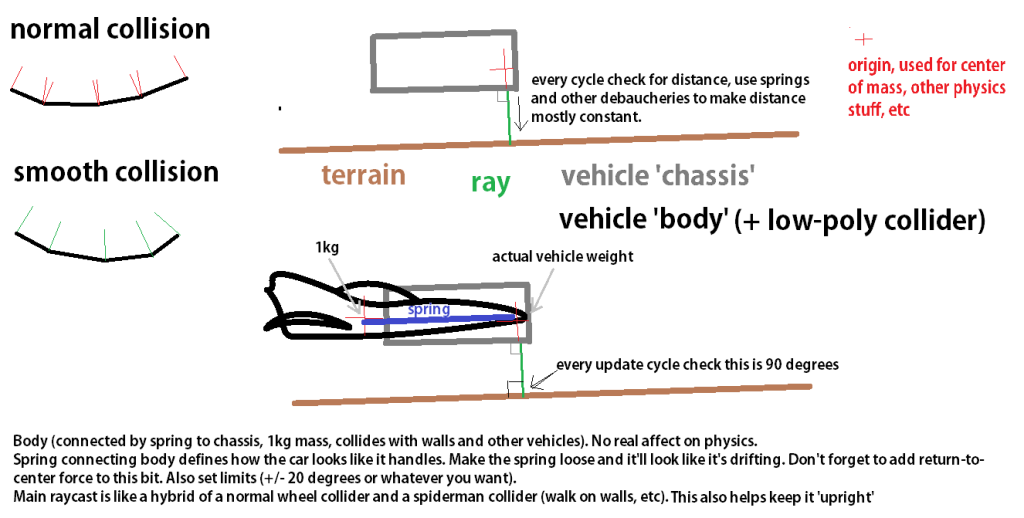
My idea was fairly simple, to create a small array of ray traces in a cross formation which simply fed back no other information,than the world space location of the hit.
I could then use them to feedback rotation information, by taking the direction vector from eg. The rearmost raytrace impact and the forwards most impact point, to produce what I could use as my new x axis. and vice versa for left -> right.
It wasn't entirely simple to work out and I ran into a bunch of complications along the way, for a long period the vehicle would lock to a specific axis of the surface it was on, but only on an angled slope. The original model that was causing this I later realised was retrieving the local impact location of the ray traces which was causing confusion in the rotators.
It also originally just combined the two rotation outputs. where only one of them took yaw information from the hull. I later realised that it would be a lot simpler to create one rotator and add the individual axis values together.
When the system was finished and working I threw a Rinterp to lower out the speed at which the rotation happened and make any accidental bumps in the road surface less noticeable by producing a smoothing effect.
Sunday, 26 October 2014
Thursday, 23 October 2014
Research into a different physics setup
http://answers.unity3d.com/questions/769705/angled-direction-vector-from-raycast-normal.html
http://www.polycount.com/forum/showthread.php?t=93049
Tuesday, 21 October 2014
Racing prototype - Physics breakdown
So here I've got my two first prototypes for a racing game that I'm working on, and want to breakdown how the physics currently works. Mostly because I want to keep note of it, and I'm planning to replace it with a (hopefully) better and less CPU heavy system.
Space dust racing was a game I looked at when working out my vehicle physics, they have a pretty good breakdown of how it all works, or at least the theory behind it. So this was a good starting point for me to base my scripting around.
So, here's how it works. I draw four ray traces down in local z space. It then grabs the contact point and divides it into the length of the raycast to give a number between 1 and 0 which is then scaled by a factor and applied as a force at the source of the raycast.
It also takes the upwards velocity of the vehicle into account during theese calculations and attempts to dampen it to remove the perpetual bounciness that the system was giving me in early testing.
The Blueprint that handles the suspension system.
The acceleration is simply handled by setting the vehicles velocity in its local orientation by an incrementing amount when the forwards/backwards buttons are pressed. To stop it from accelerating to an infinite amount the vehicle has linear velocity dampening enabled, which is also what causes it to come to a stop when there isn't any force being applied.
The blueprint that handles acceleration
To simulate traction, the vehicle gets the forwards velocity of the vehicle then gets the Y component of the vector, scales it by an amount and then applies a force in the opposite direction of the Y vector.
The blueprint that handles traction.
The current setup also has some other features such as a sstabilizerarray that rotates the vehicle if it starts to tip over too far. A lot of the functions in the system are also vetted by an "is airborne" check which simply detects via a ray trace if there is a surface directly underneath the vehicle, which allows me to alter physics settings depending on the vehicles state, That ray trace also finds out what phsyical material is under the vehicle, allowing me to do things such as lowering the tracion on certain sufaces.
The blueprint that handles the stabilizer array
Subscribe to:
Comments (Atom)